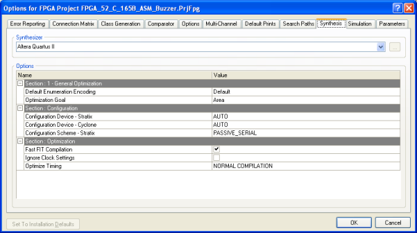
- #Altera quartus ii how to
- #Altera quartus ii software
- #Altera quartus ii Pc
#Altera quartus ii software
Start the Nios II Software Build Tools for Eclipse. Requirement: Steps in the previous section "How to build the binary" are completed. #Altera quartus ii how to
How to import the project into Nios II Software Build Tools for Eclipse for debugging purposes
 To Download the ELF file to the target, change to the openPOWERLINK subdirectory: openPOWERLINK_ROOT/apps/demo_cn_embedded/build/altera-nios2. Program the SOF file with Quartus II Programmer into FPGA.įor the TERASIC_DE2-115 (INK) it is located in the following subdirectory: openPOWERLINK_ROOT/hardware/boards/terasic-de2-115/cn-single-gpio/quartus/cnSingleGpio.sof. (This will download the bitstream to the FPGA and afterwards the elf to the Nios II CPU.) Note: You can combine step 2-3 by typing the following into the "Nios II Command Shell": $ make download-all The script's help message can be printed with -help. If you want to debug the demo, use the -debug option. Rebuild the Makefile also if the Nios II Design was changed inside Qsys. Run make to build the ELF file after changing the sources. If you want to change to another board, use the -board option: $. Note: The script uses the TERASIC DE2-115 CN demo by default. Run script create-this-app to create the Makefile for the demo. Use the software design available in the openPOWERLINK subdirectory apps/demo_cn_embedded/build/altera-nios2. Start the compilation in the Quartus II window via menu Processing -> Start Compilation. Close Qsys when the generation has finished (shown as information output). Open the Qsys file ( *.qsys) in the demo's directory, change to Generation page and press the button Generate to generate the Nios II system. Open the Quartus project file *.qpf with Altera Quartus II according to the demo you want to use. Steps 1-5 can be carried out by executing $ make all in a "Nios II Command Shell". The Altera Qsys subsystem cn_pcp is located in hardware/ipcore/altera/qsys. The subdirectories starting with cn- refer to designs for POWERLINK CN demos. The Altera Quartus II projects are located in hardware/boards//quartus. Switch on the board with the Power button (SW 18). Set the POWERLINK Node ID to '1': Push SW 10 to upper position. Connect one Ethernet port of the INK-board to a POWERLINK MN with the delivered cables.
 #Altera quartus ii Pc
Connect the USB-Blaster to your PC via USB-cable. Set the jumpers JP1, JP2, JP3, JP6 and JP7. Download the user guide for the board from the Terasic Website. POWERLINK network with managing node (MN). Experience with this development environment is required. Altera Quartus II v13.0 SP1 (Web Edition is also possible).  Development Board TERASIC_DE2-115 (INK Board). Process data: 4 bytes input and 4 bytes output. PCP "demo_mn_embedded": apps/demo_cn_embedded/build/altera-nios2. The software project for the PCP can be found in apps: Note that hardware designs can be ported easily to other platforms by reusing the Qsys subsystem instances in hardware/ipcore/altera/qsys/cn_pcp!
  Single GPIO demo: hardware/boards/terasic-de2-115/cn-single-gpio. The following CN FPGA design is available for the TERASIC DE2-115 INK board: Additionally, a hub IP-Core is provided enabling daisy chained networks. The Ethernet interface is built with the POWERLINK-optimized controller openMAC, which enables e.g. The CN implementation applies the soft-core processor Altera Nios II to execute the protocol stack. The POWERLINK CN on Altera FPGA implementation utilizes IP-Cores available in Altera Qsys and provided with the openPOWERLINK stack in the directory hardware/ipcore.


